Construction Concept
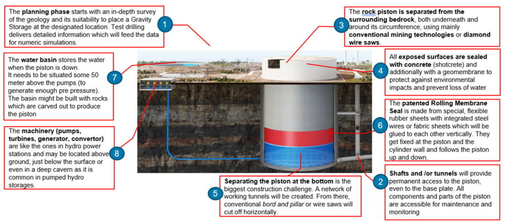
1. Planning phase
2. Drilling/excavation of access shafts and tunnels
3. Excavation/separation of the piston and its walls and base
4. Sealing and strengthening of excavated surfaces using concrete connection to high voltage power grid
5. Separating the bottom
6. Installation of rolling membrane seal around piston
7. Construction of water reservoir
8. Installation of machinery and electrical plant and connection to high voltage power grid
Planning phase
The geological conditions must first be assessed in detail in a feasibility study.
Once the feasibility has been confirmed, the detailed planning starts.

Excavating tunnels and the piston
For any sizes, tunnels or shafts must be installed in which vehicles and people can be transported to the bottom of the piston, so that they can setup the technical equipment.
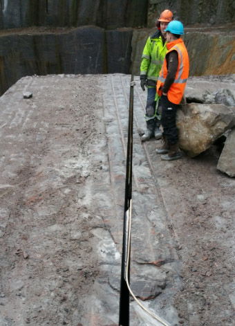
The separation of the piston will be the main and most lasting step of construction. The piston is exposed using circular cutting so that there is approximately a 2-3 meter distance between the outer surface of the piston and the shaft, in which the piston will later move up and down. Therefore there is enough space so that this area of the surface is accessible and can be covered with concrete to ensure stability and geomembranes or HDPE foil to ensure watertightness.
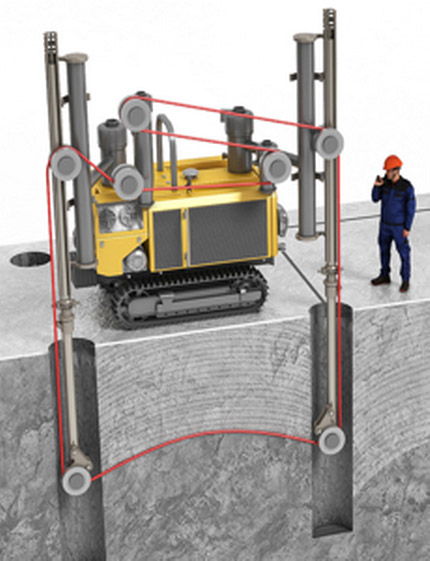
For efficient executing we see options of different technologies which might be applied depending on the geology, the availability of machines and the ability and experience of the construction company: diamond wire saws or conventional mining technologies.
In future, there will be much more efficient methods to create tunnels like with heat-driven technologies offered by earthgrid or petra. It is important to protect the rock from any harm, which is why blasting should be avoided.
Later in operation phase, the shafts and the tunnel system will provide permanent access to all areas of the piston. All components and parts of the piston are accessible for maintenance and monitoring.
Sealing
Sealing the surfaces
All exposed surfaces are sealed with shotcrete (regular concrete) and covered by geomembranes and/or HDPE to protect against environmental impacts and prevent water leakage in the pressure area and water ingress in the outer area and to stabilize the piston.
Sealing the pressurized water
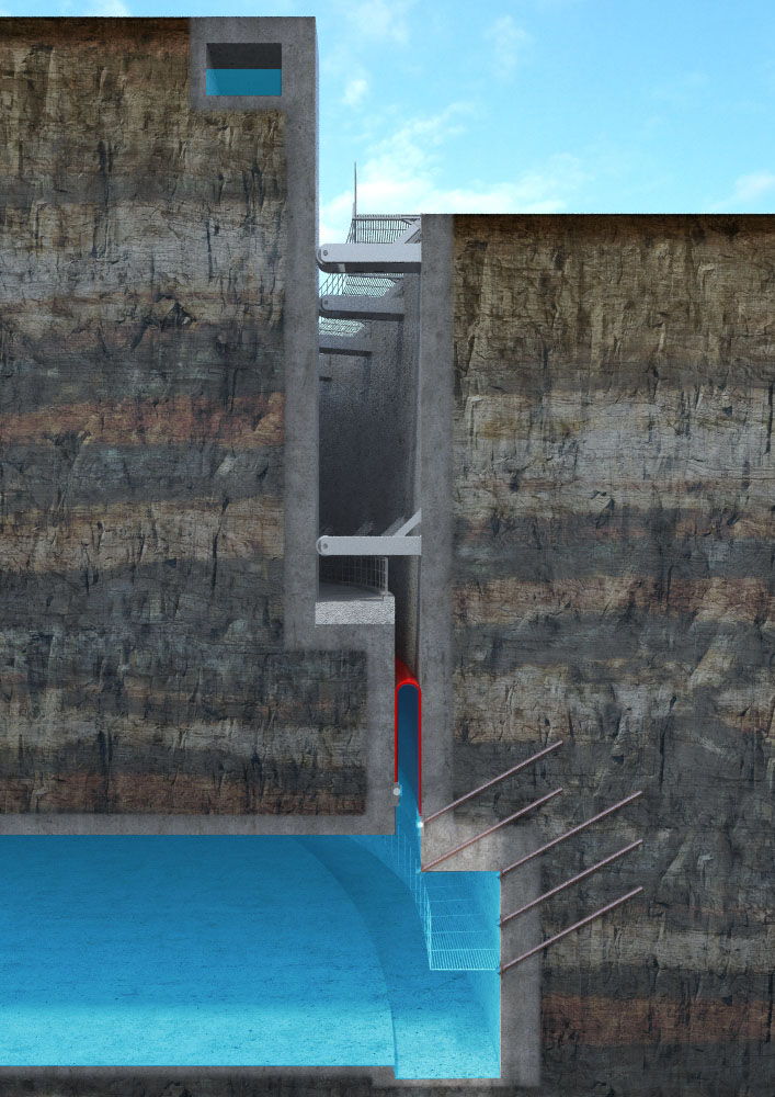
We have devoted a large part of our development work to the seal. Its challenge is on the one hand is the load capacity with the prevailing pressures, and on the other hand, the necessary bending radius of approx. 20 cm, which is required during unrolling.
The solution to the key challenge of sealing the gap between the piston and the cylinder, retaining the highly pressurized water below, is a “rolling membrane” which is securely connected to both piston and cylinder. The rolling membrane is assembled in situ from individual membrane elements that connect radially from the piston to the cylinder. The membrane elements, similar to conveyor belts as used in the mining industry, consist of vulcanized rubber reinforced with steel cables or aramid fibers.
Construction of water reservoir
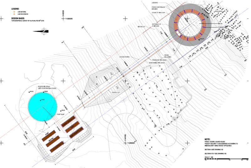
The basin stores the water when the piston is down and will be built quite basically. It can be compared with a basin from pumped hydro storage. One idea is to use the bricks of rock available after cutting the piston as material to construct walls for the basin.
Machinery & Operations
The operating life of the system is practically unlimited, since its main component – the rock mass – is extremely durable. The operating equipment, such as pumps, turbines and generator, can be designed for a service life of 60 years or more, and can then be replaced as required. The technical operation is very similar to how pumped storage plants are run.
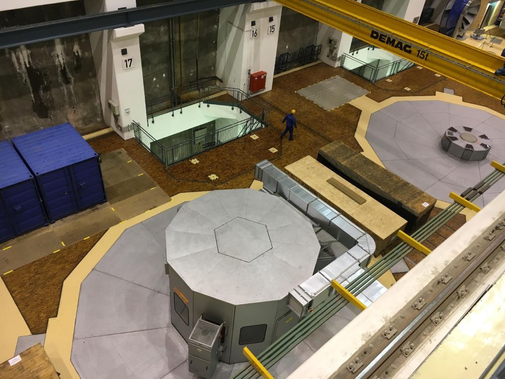
The machinery (pumps, turbines, generator, convertor) are like the once in hydro power stations and may be located above ground, just below the surface or even in a deep cavern.
The type of pumps and turbines will be chosen according to the business case of the investor or operator. Fast ramping pump-turbines are needed if the storage shall earn its money in the reserve power market. Slower and therefore cheaper pump-turbines will be installed if you go for wholesale market or back-up for low generation.
Gravity Storage is a large-scale technology which works only cost efficient at a minimum size of 500 MWh. Consequently, it will be usually connected to the high-voltage grid. It takes a converter station and a regular grid connection like in any hydro power station.
Summary
- The value of Gravity Storage is created by the fact, that doubling the diameter results in 16 times more storage capacity (4th power) as constructions cost only grow linear.
The bigger the piston, the lower the costs per kWh. - For this reason, there is a minimum size for economic feasibility starting from about 150 meter as a diameter. For sizes below other storage solutions will be more suitable.
- The relation between diameter and height can be chosen according to geological constraints. But, if possible, height is longer than diameter to achieve higher storage capacity. The piston shall be lifted at a maximum of about 40% of its height to ensure stability.
- You can put the pumps and turbines into a cavern or a hall close to surface.
- Major part of the excavating work will be done by either conventional mining techniques or new methods like wire saw or potential new techniques like heat based or plasma drilling.
- All exposed areas will be covered with shotcrete and geomembrane.
- The Seal is a major component. It will be flexible and can withstand pressures of more than 100 bar.


